Search Microcontrollers

Friday, August 14, 2015

TI RTOS - thread synchronization

I don't have much free time these days, but when I have a spare hour, I like to play with the TI RTOS, following the great online workshop I discussed in my previous post.

The BIOS (Kernel) of the OS allows you to create threads (functions) that run with different priorities and that respond to an hardware interrupt (Hwis) or a software generated "event" (Swis, Tasks) or simply run continuously whenever the OS is not busy with other stuff (Idle).

All that is quite cool and also rather easy to implement, but soon you discover you may need to implement some sort of synchornization between your threads, eventually passing values from one thread to another.
Say you have a Hwi that triggers whenever data is received on the UART, it sends the buffer to a Swi that reads it and interprets data (i.e. commands you are sending remotely, let's imagine it's ASCII based and at every \n you mark the end of a command).

What happens is that once you receive a command, you want to react accordingly and this reaction may take a few CPU cycles, for instance to turn a stepping motor X steps in a given direction.
Meanwhile your UART is still receiving other commands.

You see it's easy to get in a difficult situation where buffers are overrun or changed while you are using them.

The worst solution to exchange data across the different threads is to use global variables as buffers, these will easily get manipulated while you are using them.
sure, there are a few ways to protect your system from this to happen, but most of those "solutions" are likely to introduce even worse problems.

But hey, we have an OS, remember?
The RTOS has built in capabilities to regulate the execution of the tasks.

Semaphores

A Semaphore can be used to pause (pend) a task untill another task tells it (post) to run.

It is somehow similar to an event, but it does not trigger a function (like an event would do), instead it tells it (whenever the bios scheduler decides to give back the Program Counter to it, based on priority settings) to keep running.

Example 

void myTask()
{
  .. do some init stuff...
  while (1) // run forever
 {
    ... do some other stuff ...
   Semaphore_pend(myCoolSemaphore);
   ... get the data and use it...
  }
}

It is cool, indeed, but if we need to echange data, the Semaphore is not enough.

So, there are features in the OS that allow one thread to send a buffer with a message.
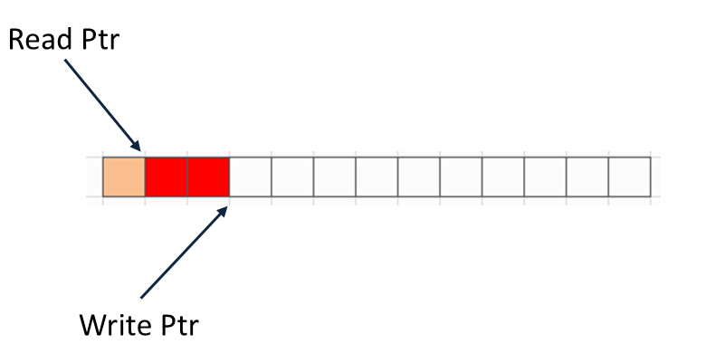
This message can be in a Queue or in a Mailbox.

Queues and mailboxes are slightly different, the main difference is probably that messages in mailboxes are in fact copies of the data, meaning that the sender and the receiver do not share the same memory locations when accessing the data, while queues pass pointers.
Another important difference is that mailboxes have built-in semaphores, while Queues don't, you need to provide a semaphore for synchronization purposes.

The overall idea is that along with a synchronization signal you can send data, i.e. the buffer containing the command.
However we can have several mails in a mailbox, making the system automaGically multi-buffered.

So, going from a single buffer to a n-buffer solution if using queues and mailboxes is mainly a configuration task (you set up values in the GUI, no coding needed for this).


The picture (app.cfg edited in CCS 6.1.0) shows a double buffer implemented with a mailbox with 2 max messages.

The example, taken from the TI RTOS Workshop (see previous post) lab 9 does the following:

1) An Hardware timer generates an interrupt every 500ms
2) An Hwi function associated to the timer int posts a semaphore

void Timer_ISR(void)
{
    TimerIntClear(TIMER2_BASE, TIMER_TIMA_TIMEOUT);
Semaphore_post(mailbox_queue_Sem);
}

3) A mailbox management task waits (pends) for the semaphore and when it receiveds a green light, it posts to the mailbox.
Notice that in this case the "data" is generated here (msg.val is toggled).

void mailbox_queue(void)
{
  MsgObj msg;
  msg.val = 1;
  while(1)
  {
   msg.val ^= 1; // toggle msg.val (LED state)
   Semaphore_pend(mailbox_queue_Sem, 
                  BIOS_WAIT_FOREVER);
   Mailbox_post (LED_Mbx, &msg, 
                  BIOS_WAIT_FOREVER);      }
}

4) A task that actually reacts on the data (toggles a led) waits for the mailbox

void ledToggle(void)
{
  MsgObj msg;
  while(1)
  {
   Mailbox_pend(LED_Mbx, &msg, 
                BIOS_WAIT_FOREVER);
   if (msg.val)
   {     // turn LED on

    GPIOPinWrite(GPIO_PORTF_BASE,
           GPIO_PIN_1|GPIO_PIN_2|GPIO_PIN_3, 8)  
   }
   else
   { // turn LED off
    GPIOPinWrite(GPIO_PORTF_BASE, 
            GPIO_PIN_1|GPIO_PIN_2|GPIO_PIN_3, 0)
   }
  }
}

We can observe what happens thanks to the UIA (Unified Instrumentation Architecture) that allows to interface with the OS via the JTAG port and gather execution details.


In the picture you can see that while the system is Idle (green line) a semaphore is posted (first green flag) by the Hwi function.
Control is handed over the mailbox management function (higher blue line) which is pending on the semaphore (first red flag).
It executes toggling the msg.val and then posts a mail (second green flag), then goes back pending on the semaphore again (second red flag).
Only then the bios scheduler (lower blue line) passes the control over to the ledToggle function (red line) which is pending on the mailbox, it gets the message (third green flag -it is green because it does not block the task, and it does not block the task because there is a message in the mailbox), manages the led based on the value in the message and finally waits again for the mailbox (third red flag).
At this point there are no other messages in the mailbox, so the flag is red, the task gives back control to the sceduler.
Guess what happens when a new timer int is fired?
Yup, rinse & repeat.

Neat eh?
If you are interested in knowing more on the subject, I encourage you to try the free TI RTOS Workshop, the example illustrated here (and the relative code) is taken from the Lab 9 material.

Thursday, August 6, 2015

Playing with the TI-RTOS

I always thought that dealing with an RTOS was some kind of nightmare.
Well, looks like I was wrong and yet again we prove that most of our beliefs are generated by ignorance, I happen to have a lot of it! :)

First thing first, what is an RTOS?

Real Time Operating System, that's what the acronym stands for, but to give a better explanation, we can say it is an Operating System that runs on micro-controllers and eventually CPUs.
That's the "OS" part, now for the "RT" one we can say that it is designed to have a minimal overhead and allow, depending on the clock cycle of the used hardware device, a quick reaction to events.

Say you want to control an electric motor and you feed back a number of signals (i.e. actual speed from an hall effect sensor , some user controls etc.), then you want the system to react as "realtime" as possible, you don't want you motor to react 5 minutes later because you are installing some windows updates.

Yup, you should not expect live updates by default in an RTOS :)

When you have many things potentially happening at the same time, then you normally use a loop that scans them (the quick and dirty solution) or better you set up some interrupts and maybe some timer based functions.

If you have an OS, then you can use threads.
An RTOS gives you the ability to schedule threads, neat eh?
However in giving you that functionality it makes sure that this does not generate much overhead and it allows you to define how to prioritize them.

If you played with systems running with multiple interrupts, then you know about nesting interrupts and while in theory this is pretty straight forward, but in an application that should not miss any interrupt and provide a reliable event handling this can be problematic.

You guessed, the RTOS threads make this an easier task.

... but... yeah... when I am dealing with an mcu I might not have much of power to run an OS you may think.
Well, the tiny MSP430G2 runs at 16Mhz, 16 bits, not much, right?
My old 80286 desktop computer was 16 bit , 10MHz and I thought it was running MS-DOS pretty neatly!
So, in reality, it depends on the OS you are using and an RTOS gives you WAY LESS than MS-DOS, and this makes it perfectly usable even on a MSP430 launchpad (don't try to install windows 10 on it, tho)!

TI created its own RTOS (and they called it TI-RTOS) and it is available for different kind of platforms : MSP430, CortexM4 (Stellaris, Tiva), C28x, C6x etc.

If you have any kind of launchpad, chances are you can freely use the TI-RTOS!
In CCS6.1.0, just go to the CCS App Center and download the version that matches your device


As in its best tradition, TI provides amazing training material, including an extremly well done workshop (yup, for free, online) titled "Introduction to the TI RTOS Kernel Workshop".
The instructor Eric Wilbur is absolutely great in those videos.
Lab activities help tremendously in understanding the tasks at hand and in discovering how much you can do with the OS and the related tools.

We said the RTOS has some kind of smart "scheduler" that allows you to run threads, but that's just a small (although important) part of it.
It provides memory management, debug functionality and GUI configuration features.
Also it comes with drivers, provided in a library, these reduce the need to access the system low level, instead they give you APIs you can use to interact with the rich hardware present in the MCUs.

I am currently enjoying the labs of the workshop, I suggest you do the same, but for those who are too lazy for it, I will post here some summary activity, this will be my way of taking minutes about what I do.

Meanwhile, if you think a typical "arduino like" application, it has a skeleton like the following


void init()
{
  // hw initialisation
}

void loop()
{
 while (1)
 {
   dosomeStuff();
   doSomeOtherStuff();
 }
}


a TI RTOS application instead looks like :

void main(void)
{

   hardware_init();// init hardware via Xware
   BIOS_start();
}


There is no more a while(1) loop because the BIOS is handling the task scheduling, you simply ask the bios to start and it will take care of the different threads.
Threads exist in different flavors and they can be assigned different priorities.
The easiest form of a thread is an idle function, which is executed with the lowest priority by the idle thread, basically when the CPU / MCU does not have anything more important to do.

Creating an idle function is fairly easy, say we have a function that toggles the onboard LED (code taken from lab 4 of the before mentioned workshop and slightly modified by myself)

void ledToggle(void)
{
if(GPIOPinRead(GPIO_PORTF_BASE, GPIO_PIN_3))
{
GPIOPinWrite(GPIO_PORTF_BASE,                
                   GPIO_PIN_1|GPIO_PIN_2|GPIO_PIN_3, 0);
}
else
{
GPIOPinWrite(GPIO_PORTF_BASE, 
                   GPIO_PIN_3, GPIO_PIN_3);
}
delay() // create a delay of ~1/2sec
}

then you just need to register the function as an idle, which you can do in the GUI simply like this :

Pretty simple eh?
Now, you may think that the delay function call is blocking, but this "blocking" behavior only affects this specific thread, it does not prevent other threads, with higer priority, to run in parallel.

Now I guess you can see how the whole OS thing starts to make sense and at the same time, it does not necessarily add complexity to your application.

Give it a try, it's fun!


Friday, July 31, 2015

Internet of Things, sub 1GHz radio and more

If you follow my blog, you probably realized that I am a supporter of technology company that engage in quality education activities.

Texas Instruments is one of them, so I used some of their products to learn and to share my experiments in this blog.

Not long ago (July 16th 2015) TI, together with Element14, offered an interesting free webminar with the captivating title : "From Start to Finish: Creating a Multi-Node Cloud-Connected Sensor Network with Texas Instruments LaunchPad Development Kits"

I know, now you are expecting a "...but...".
Nope, no "but", it was simply great, I strongly suggest you check it :)

IoT is becoming easier and easier, both from software and hardware point of view.
Software is kind of my thing, so, that was never really a main issue for me, or better it was an issue I knew how to deal with, but hardware used to be either hard or expensive (or both).
Gone are those days and there are plenty of products (from various vendors) that really speed up your prototyping.

TI definitely supprots them with great learning resources, this webinar, presented by Adrian Fernandez , TI Microcontroller Development Experience Manager was one of them.

You can see his video here:


Now, the IoT part is cool, but combining it with sub1GHz radio is even better (and as Adrian shows, quite easy).

So, IoT means you have some device that can communicate with the internet, usually acting as a node connected to an ADSL router.
If you have 10 sensors spread around your house, you can definitely have 10 nodes, all connecting to your router and doing their stuff.
It works, possibly, but it's not the best solution.
Back in the days we used to add a RS485 interface, run a few cables here and there and generate a wired network of sensors to the "managing" node, the one that eventually communicates with the internet.
Also works.
Then the nRF24L01 radio came out, working at 2.4GHz.
That one is cool, low cost, not too difficult to use.

Can we do even better?
Turns out we can.
The TI CC110L chip allows Radio communication at 433MHz (and other sub 1GHz frequencies), for wireless connectivity in a low power package and low frequencies give you more "bang" for your milliAmps.
TI provided a boosterpack for the launchpads featuring this chip, that makes it easier to implement a prototype, particularly because being part of their standard ecosystem, it comes with software libraries.
This is the boosterpack FedEX delivered few minutes ago :


The Kit gives you two CC110 (@433MHz) nodes on a shield.
Now, why did I receive the boosterpack?

Well, in my personal opinion this story redefines the concept of "cool".
So, I joined this free webinar, which was extremely informative and fun, extremely "hands-on".
That, in my book, is "cool".
TI delivers free software tools and rather cheap hardware to play with and practice what you learnt, that's also cool, no?

But what goes behind the concept of cool is that I got the boosterpack, plus a MSP430FR5969 launchpad AND a CC3200 Wi-Fi launchpad FOR FREE, delivered from Texas to the old continent.

Apparently I got lucky (not sure how many winners were there), but simply answering a very short quiz after the webinar I won all those toys.
It's Christmas in July! :)

I am currently extremely busy with a couple of projects, but as soon as I can spare some time (hopefully really soon), I plan to test the new toys in an industrial automation project, collecting production data from machines and pushing them to the web.
I am currently using a BBB for that, but there is a case for a different architecture, possibly on top of the existing one.

Until then, well, thanks Adrian and TI!


Saturday, June 13, 2015

Should rights be "forever" in a ever-changing world?

We fight for our rights, many, if not most, of our heroes are those who gave their lives to obtain and preserve some rights we now hold dear.
These include freedom, equality (Liberté, égalité, fraternité anyone?)  down to some more modern era/more detailed and specific rights such as (in some countries) refuse to join an army, work-life balance, health, even a minimum wage or a "citizenship income" in some places etc.
People should not work more than 8 hours a day (may vary slightly by country).
Took a while to achieve that and we consider it an important milestone in human rights.
I am all for it, don't get me wrong, in fact it might even be the case we should at this point (some did) reduce those 8 hours.
But, what IF it does not make anymore sense, meaning that in a given context, a given society, that does not work anymore, it is not sustainable.
Would it be still a right?

Now, the one I would like to discuss is even more radicated in our culture, in a way that every single politician in every single campaign would advertise he/she will do everything to boost it.
Politicians do their research (with our money) and even the dumbest of them are able to select their stands on these topics, so I know I will attract a lot of hatred reactions just for discussing the matter, but, hey, go ahead, hating is one of your rights after all (and I am not running for office anytime soon) :)

The right to have a family.
Ok, ok, I hear you booing already, once you are done, can we have a serious discussion about it?
The "light" version of it says that a men and a woman should be able to marry.
A slightly modernized version says that two humans, regardless of their sex and their sexual preferences, should be able to marry.
I am fine with both versions, no issues here.

Now, in most places this extends to "a family"  in the sense you have rights to have children.
Children are cool I guess, who could argue with that?

Before we go ahead, I know in these discussions we are all biased, so I will just declare my bias upfront, for the benefit of a rational and honest discussion :
I have no children, never married, never wanted to, never felt the urge to create a family, for a number of different reasons.
At this point I guess you MUST be hating me a little bit already, right?

Ok, now, back to the point.
Rights to have children in general means a lot of things which go beyond the actual fact of having one or more babies.
It ties into making it easier to families to support them, in other words it is like the society is promoting families.
In most countries the society recognizes that raising children is an expensive task, so you get a little bit of tax reductions, some maternity leave rights (for both parents) etc.
These "allowances" are granted  using the society resources (mainly collected taxes) as in general such resources should go to support the citizen's rights and well being.
If something is a citizen's right, then I totally agree that the society should do whatever possible to favour its implementation and even promote it.
But is it?
Is transmitting your DNA really a right and, in a more general sense, can we say that a right is still a right regardless of the context, forever?
Or can we say that rights are a mere product of our culture, which, in turn, generates from our history?

Let me introduce another bias I have : I am an atheist (which I find a funny definition, but most of you would call me that way) and have no holy book telling me what's good or wrong. I do need to find it out myself and for this reason I ask myself several questions and sometimes discuss them with others.

So, it is clear that the urge of transmitting our DNA is present in all animal species, but normally they (slowly) evolve, both genetically and "culturally" in a  way that affects their reproduction rate according to the needs.
A wonderful explanation of this concept (although with the opposite problem) can be found in the speech that Douglas Adams gave for TED, about 1 third in the speech, when he tells the story of the Kakapo.

I strongly encourage you to watch the full speech as D.A. was a phenomenal speaker on top of being a witty and creative writer.


(Douglas Adams : "Parrots, the universe and everything")


The "problem" with humans is that we became remarkably efficient in modifying the environment around us to suit our needs, so, when the environment was supposed to counter our expansion, we fought back and somehow "won".


Going from the Kakapo to another animal that might be more familiar to all of us, let's consider the cat.
I love cats, in fact I live with two 10 yr old females since quite some time.
Most of the people who love cats agrees -like I do- that it is a good thing to spay or neuter them.
In the wilderness, the chances of survival of a cat in his/her first years are pretty slim, plus when the populatuion grows in a given area, it is regulated by competition for food or territory.
So they needed to procreate very quickly, the fittest would generally survive and maintain the specie alive.
Since most of the cats now live with humans, they share the "benefits" of the modified environment, i.e. we provide medical care and food for them which extends greatly their life expectaion and dramatically reduces chances of deaths for lack of food etc.
Is the cat risking extinction because we neuter and spay most of them?
Not that I am aware of, in fact it seems to me that population control, given the actual context, is being a benefit for the cat specie.


Now, why would it be different for humans?
Take a look at this chart :


Does anybody see any alarming trend there?
Humans in 1960 : 3.000 Millions
Humans in 2050 (projection) : 9.000 Millions
( 3x in 90 years)


Cat's chart would have been similar (worse actually, because of their high reproduction rate) if we did not take actions. We realized that having an average of 3 cats per square meter aound us would have been quite an issue for everybody, including them.
Cats have no right to procreate in fact, it did not take long to us to negate that one to them, few complained.

Now, back to humans, I believe it is culturally difficult to "cap" the number of children a family should have (it is somehow happening in some places), mainly because we feel that having them is a right.
For the same reason we still try, as a society, to encourage families to have children.
But, does it make sense?

Shouldn't a behavior that actually damages the society, the human kind and the whole world alltogether be considered more like a crime, rather than a right?
I know this is a strong statement, but it is really a question.
I am not immune to cultural biases either, so that question scares me as well.
But I do know that sometimes truth can be scary, because it shakes our belief system, but I grew accustomed to this, I know that scary or not does not change the fact that it is the truth.

I also imagine many of you will say things like : "If your parents thought the same thing, you would not be here blogging" and yes, I can see that, but, so what?
Isn't this an incredibly egoistic thing to say?
Each one of us feels special, but from the community point of view we are just another human contributing both with good and bad interactions.
I try my best, most of the time, to ensure that my contribution to the society is worth the air I breathe and the food I eat, sometimes I question it (and I believe that's a good exercise).

Can our society still consider that having babies is a human right?
Should rights be demoted to "cultural habits" and eventually to "bad habits coming from a past, different, context" when they damage the society?

Pick your answer and try to be consistent with facts.

Thursday, May 21, 2015

Cortex M3 - SPI / 1

I have been playing with SPI a few times, but never on a Cortex M3 using CMSIS.

That, by itself, it should be a good reason to dig into this topic, however I have a nice project in mind and it will require SPI communicatin, so... let's  get to it!

Some basic stuff first :
SPI uses four pins: MOSI (Master Out Slave In), MISO (you guess it), CLK (clock) , SSEL and as Chip enable/select to activate the slave, normally a simple GPIO pin on the master.

NXP Cortex M3s implement a variation of SPI called SSP (Synchronous Serial Port) which supports the "old" SPI.
In the LPC1768 there are two SSP peripherals called SSP0 and SSP1.

The LPC17xx manual says:

"The two SSP interfaces, SSP0 and SSP1 are configured using the following registers:

  1. Power: In the PCONP register, set bit PCSSP0 to enable SSP0 and bit PCSSP1 to enable SSP1.
    Remark: On reset, both SSP interfaces are enabled (PCSSP0/1 = 1).
  2. Clock: In PCLKSEL0 select PCLK_SSP1; in PCLKSEL1 select PCLK_SSP0. In master mode, the clock must be scaled down.
  3. Pins: Select the SSP pins through the PINSEL registers and pin modes through the PINMODE registers.
  4. Interrupts: Interrupts are enabled in the SSP0IMSC register for SSP0 and SSP1IMSC register for SSP1. Interrupts are enabled in the NVIC using the appropriate Interrupt Set Enable register.
  5. Initialization: There are two control registers for each of the SSP ports to be configured: SSP0CR0 and SSP0CR1 for SSP0, SSP1CR0 and SSP1CR1 for SSP1.
  6. DMA: The Rx and Tx FIFOs of the SSP interfaces can be connected to the GPDMA controller
Remark: SSP0 is intended to be used as an alternative for the SPI interface, which is included as a legacy peripheral. Only one of these peripherals can be used at the any one time" 
(@NXP LPC17xx user manual)

It seems to me this is a pretty good checklist.

1) Power ON


Power CONtrol for Peripherals (PCONP) is the register we use to turn the SSP (or any other) interfaces on:

  LPC_SC->PCONP |= (1 << 21); /* Enable power to SSPI0 block */
  LPC_SC->PCONP |= (1 << 10); /* Enable power to SSPI1 block */

Normally we just need one, I reported the lines for both so you can decide which one to use.

2) Clock in

The Peripheral clock selection is done via the PCLKSEL0 and 1.
Each peripheral uses 2 bits

00 : PCLK_peripheral = CCLK/4 00
01 : PCLK_peripheral = CCLK
10 : PCLK_peripheral = CCLK/2
11 : PCLK_peripheral = CCLK/8

SSP0 uses bits 11:10 of PCLKSEL1 and SSP1 uses bits 21:20 of PCLKSEL0

LPC_SC->PCLKSEL1 &= ~(3<<10);  /* PCLKSP0 = CCLK/4 */
LPC_SC->PCLKSEL1 |=  (1<<10);  /* PCLKSP0 = CCLK */

LPC_SC->PCLKSEL0 &= ~(3<<20);  /* PCLKSP1 = CCLK/4*/
LPC_SC->PCLKSEL0 |=  (1<<20);  /* PCLKSP1 = CCLK */

3) Pins

Here we will set MISO, MOSI and CLK pins, plus you need to remember to set 1 GPIO as output to enable the slave, in this example we will assume you are using GPIO P1.21 as SSEL (Slave Selection / Enable).
Normally SPI slaves are selected active when SSEL is LOW.

A summary of the available configurations for SSP pins :


 /* ----> SSEL : output set to high. */
LPC_PINCON->PINSEL3 &= ~(0<<10);   /* P1.21 SSEL (used as GPIO)   */
LPC_GPIO1->FIODIR   |=  (1<<21);   /* P1.21 is output */
LPC_GPIO1->FIOPIN   |=  (1<<21);   /* set P1.21 high*/
  
 /* ----> SSP0 : SCK, MISO, MOSI  */
LPC_PINCON->PINSEL3 &= ~(3UL<<8);       /* P1.20 cleared  */
LPC_PINCON->PINSEL3 |=  (3UL<<8);       /* P1.20 SCK0  */
   /* P1.23, P1.24 cleared        */ 
LPC_PINCON->PINSEL3 &= ~((3<<14) | (3<<16)); 
   /* P1.23 MISO0, P1.24 MOSI0    */ 
LPC_PINCON->PINSEL3 |=  ((3<<14) | (3<<16)); 

 /* ----> SSP1 : SCK, MISO, MOSI  */
LPC_PINCON->PINSEL0 &= ~(0x3F<<14);  /* P0.7,8,9 cleared  */
    /* ... an then set to function 2 */
LPC_PINCON->PINSEL0 |=  (2UL<<14) | (2UL<<16) | (2UL<<18);

4) Interrupts

As suggested by the checklist, we will use the SSP Interrupt Mask Registers SSPxIMSC.


As you can see, these interrupts are used to identify error conditions or FIFO status to ease buffered communication.
Since SSP is a synchronous communication (unlike the UART), there is no point in having a RX data ready interrupt.
In fact, each time you want a slave device to send you some data, using SPI / SPSS you explicitly have to ask for it (polling), meaning you should also be already listening for it to arrive, no need for an interrupt.

Should you need to implement some more advanced control, feel free to enable those interrupts, in that case you should check the SSPxRIS (Raw Interrupt Status), SSPxMIS (Masked Interrupt Status) and SSPxICR (Interrupt Clear) registers.

5) Initialisation

Ok, we definitely need this one.
What we need here is to accurately set the bit frequency, so that it will match the frequency supported by the slave device we are interfacing.
This is done via the Prescaler Register (CPSR) that divides the peripheral clock (pclk) we initially configured in step 2 (PCLKSEL0 and 1).

So, let's assume our processor is running at 100MHz, we fed the peripheral with the same clock speed (by providing a divider = 1) and now we want to obtain a 400KBit/s rate.
How do we do that?

#define sspKBps 400000
int prescaler = SystemCoreClock / sspKBps; 
/* 100.000.000/400.000 = 250 */

LPC_SSP0->CPSR = prescaler; /* for SSP0 */
LPC_SSP1->CPSR = prescaler; /* for SSP1 */

Now we need to use the SSP Control registers to specify how many bits should be transferred and which protocol -Frame Format- to use (remember, the SSP can do more than SPI, in fact it supprots TI and Microwire formats too). 
Also, we can further reduce the bit rate here by dividing the value of the prescaler, plus we can set clock phase and polarity.

  
/* SSP0 : 8Bit, SPI, CPOL=0, CPHA=0 */                                  
LPC_SSP0->CR0  = 0x0007;   
/* SSP1 : 8Bit, SPI, CPOL=0, CPHA=0 */                                  
LPC_SSP1->CR0  = 0x0007;   

The Control Register 1 (CR1) allows to enable the SSP port and to configure it as master or slave.


LPC_SSP0->CR1  = 0x0002;       /* SSP0 enable, master  */
LPC_SSP1->CR1  = 0x0002;       /* SSP1 enable, master  */

6) DMA

I am sure some day I will feel particularly brave and will have a go at it, for now, let's just say that we can enable DMA transfers for SSP ports using the SSPxDMACR registers.


Ok, with all this our SSP port should be ready for communication, at least on the Master side.

So, where do we put output data and from where do we get input?
There is a Data Register SSPxDR (we can use the low 16 bits) that is used both for RX and TX.
Why is this possible?
SSP (or SPI) is synchronous communication, meaning you cannot write and read at the same time on the line, or better, for every byte you send out, you will get a byte back.

The LPC17xx manual says :

"Write: software can write data to be sent in a future frame to this register whenever the TNF bit in the Status register is 1, indicating that the Tx FIFO is not full. If the Tx FIFO was previously empty and the SSP controller is not busy on the bus, transmission of the data will begin immediately. Otherwise the data written to this register will be sent as soon as all previous data has been sent (and received). If the data length is less than 16 bits, software must right-justify the data written to this register.

Read: software can read data from this register whenever the RNE bit in the Status register is 1, indicating that the Rx FIFO is not empty.
When software reads this register, the SSP controller returns data from the least recent frame in the Rx FIFO. If the data length is less than 16 bits, the data is right-justified in this field with higher order bits filled with 0s"

Looks like we need to check the Status Register (SSPxSR)


So, putting it all together, to exchange 1 byte we need to :

int SSP1_sendbyte(int out)
{
// enable your GPIO used as SSEL
 LPC_GPIO1->FIOCLR = 1<<21; // enable slave
 // while(!(LPC_SSP1->SR & 1)) ; // Wait until TX Empty
 // might need a grace period here, depending on the slave
 LPC_SSP1->DR = out; // output data
 // while(LPC_SSP1->SR & (1 << 4)); // Wait until SSP is busy
  while(LPC_SSP1->SR & (1 << 2)); // Wait until we have data in RX
 LPC_GPIO1->FIOSET = 1<<21; // disable slave
 return LPC_SSP1->DR;
}

In a future post we will test this with some SPI device.

Tuesday, May 19, 2015

Cortex M3 - UART / 2

Interrupts are cool.
No, seriously, if you played with serial communications you know that using an ISR helps a lot because you never know when the other device decides to send a few bytes on the line.
Asynchronous communication in full duplex baby!

So it is good to have an Interrupt Service Routine that gets the data for you from the line while you are busy doing other things.
Typically you are going to have a buffer with two pointers: one knows where to find the first location in the buffer where to write data and the other knows the first location where you did not get data out of the buffer yet.
If the two pointers point to the same lcoation, then there is no data to be extracted from the buffer.

In general this is a convenient way to buy some time and check every now and then if we received some data.


In the image above you can see an example where 3 bytes were received, so the write pointer points to the 4th location and 1 byte was read from the buffer, so the Read Ptr points to the 2nd location.
The two pointers have different values, so there is still data to be read in the buffer.
Obviously while you read and write you increment the relevant pointer, resetting it to zero when it reaches the end of the buffer.

This is one way to manage asynchronous communications, of course you could add some logic in your Interrupt handler routine to make your application react immediately i.e. when a specific character is received.
It is in genreral good practice, tho, to have as little logic as possible in the ISR routines, they should complete in the shortest amount of time possible.

Now, the funny thing is that the buffer we described is also called a FIFO (First In-First Out) buffer... which is already supported via hardware in the Cortex M3.

That's right, if you needed just a few bytes in your buffer, no need to set up an ISR, you could simply enable the internal FIFO and you can still do it even if you decide to use interrupts.

void SER_fifo(int uart,uint32_t enable,uint32_t dma,uint32_t trigger)
{
LPC_UART_TypeDef *pUart;
pUart = __get_uart_base(uart);
pUart->FCR |= (enable&0x1)|((dma&1)<<3)|((trigger&0x3)<<6);
}

The Fifo Control Register (FCR) can be used to enable the Fifo, define how many bytes should be received by it before triggering an IRQ and if it should use a dma channel to automatically copy the data to a specific memory location.
Neat eh?

@NXP

You can also reset the fifos (both the output fifo and the input fifo)... wait.. output fifo?
Yes, serial communication might be a bit slow for MCUs and imagine you need to send a few bytes out: the output fifo will be happy to store some of those bytes for you so you can go have fun doing other interesting tasks while it handles the communication.
You can do the same thing with an ISR routine or even use both at the same time.
Notice that you can activate both (RX and TX) fifos or none of them, but you cannot activate just RX and not TX or the other way round.

Now, let's see the interrupts.


The UARTxIER are the Interrupt Enable Registers for the various UARTS.
There are two interrupts we want to consider there :
- The one generated when a new byte is received (or when the number of bytes in the fifo reaches the trigger threshold, if enabled) and this is the RBR one.
- The other, generated when the line is ready to send out some new data, meet the THRE (Transmit Hold Register Empty) interrupt.
The third one is triggered when the status of the receive line changes.

#define IER_RBR  0x01
#define IER_THRE 0x02
#define IER_RXLS 0x04
pUart->IER = IER_RBR | IER_THRE | IER_RXLS;  

That line enables the uart interrupts... almost.
Actually we also need to enable the Uartx IRQ in the Nested Vector Interrupt Controller (NVIC)  which has a cool name because it does cool stuff.

switch (uart)
{
  case 0: NVIC_EnableIRQ(UART0_IRQn); break;
  case 2: NVIC_EnableIRQ(UART2_IRQn); break;
  case 3: NVIC_EnableIRQ(UART3_IRQn); break;
}

Now interrupts will be fired upon events and we should really do something with them.
To capture them we just need to define a function (one per each uart we use) with a specific name, I am using uart2 so :

void UART2_IRQHandler(void) __irq
{
   ...
}

Now we need to fill it with some good code, because I never had luck in succesfully compiling a statement like "...", so I guess it's not going to work for you either.

First thing, let's just say we want to have an input buffer which will be filled by the IRQHandler procedure.

#define UART_RX_BUFSIZE 32
uint8_t UART_RxBuf[UART_RX_BUFSIZE];
uint8_t bufWptr =0;
uint8_t bufRptr = 0;

Then we need to consider that the IRQHandler will be called for every kind of uart (uart2 in my case) related interrupt.
By "every" we actually mean as many as you can count with two fingers (or two bits), in other words : four.

This is the Interrupt Identification Register (IIR) which can be used to get the IntID, a 2 bit number that identifies which interrupt we are dealing with.


void UART2_IRQHandler(void) __irq
{
uint8_t intId;
intId = ((LPC_UART2->IIR)>>1)& 0x7;

switch (intId)
{
  case INTID_RXLS : break;// whatever
  case INTID_RDA  : 
while((LPC_UART2->LSR) & 0x1) 
                {
        UART_RxBuf[bufWptr++] = LPC_UART2->RBR;
        if (bufWptr >= UART_RX_BUFSIZE)
         bufWptr = 0;
}
break;
  case INTID_CTI  : break; // whatever
  case INTID_THRE : break; // whatever
}
}

This is a simple implementation that should provide RX interrupt handling, notice it does not check if our software buffer is overran.

Let's just add a couple of functions to get the data out of the buffer and check if we should do it.

int SER_hasBufData()
{
 return (bufWptr!=bufRptr);
}

uint8_t SER_getBufData()
{
 if (bufRptr>=UART_RX_BUFSIZE) bufRptr=0;
 return UART_RxBuf[bufRptr++];
}

And finally we can update the test program

int main(void)
{
  SystemInit();
  setpll0(25,2,3);
  SystemCoreClockUpdate();
  SER_init(2,115200);
  SER_fifo(2,1,0,0);
  while (1) 
  {
   delay(10000000);
   SER_putString (2, ".");
   while (SER_hasBufData())
   {
SER_putString (2, "Received : ");
SER_putChar(2,SER_getBufData());
SER_putString (2, "\r\n");
   }  
  }
  return 0;
}

As usual, you can get my full code here.

Sunday, May 17, 2015

Cortex M3 - UART / 1

Hello again, been a bit too busy to blog for quite some time, sorry for that.

I have a nice Cortex M3 board around since some time, it is based on a NXP LPC1768, which is quite a neat processor.
It can run up to 100MHz, has 512K Flash, 64K Sram and a nice set of peripherals.

The board itself is quite nice too, not sure you can still find it around -ebay listings below, to give you an idea on what's available-, mine is called "LandTiger" and I guess it is just some clone of some popular dev board.


That said, I wanted to play with the UART using a standard CMSIS approach.
CMSIS stands for Cortex Microcontroller Software Intertface Standard, it is defined by ARM and supported by various IDEs.

CMSIS deserves a post on its own, if you don't know it, there is quite a lot of info around already, but I might post myself a sort of "CMSIS for dummies" some time.

Regarding the IDE/toolchain there are quite a few options, currently I am using Keil uVision5 (there is a free version, codesize limited), but I also tried IAR and CoIDE (which is open source).
They all work, and all of them require a bit of fight to get the things the way you want them (at least this happened to me), I couldn't  really pick a winner in the end, but decided to stick to Keil uVision.

So, the UART.
Why the UART first of all?
Meh, getting serial communication is pretty key to allow some remote debugging, so it is a good place to start (maybe just after blinking a few LEDs).

Now, CMSIS provides a layer that gives some kind of standard helping you when you have to port your code from a device to another.
For what I can see, you cannot simply change device, recompile and hope everything works.
NXP devices have some peculairities and need to be handled differently from STM devices etc.

The way you normally manage this is to generate your own abstraction layer (or use some available libraries that do just that).

This post is about the LPC1768, but most of the info might eventually apply to other devices too, provided the register addresses will be different, but those are defined in a CMSIS include file usually provided by the vendor.

So, the LPC1768 has 4 UARTs and uarts 0,2 and 3 work pretty much the same way.
Uart1 is a bit special, so it will not be discussed here.

(@NXP)

There are quite a few registers to play with, as you can see from the LPC17xx manual.
Two easy ones : Receive Register (RBR) and Transmit Register (THR), these should not require a lot of explanations.
Can you see the specification (DLAB=0)?
That means that the Divisor LAtch Bit must be set to zero.
We use the DLAB to set the frequency divider (hence the name) to obtain specific baud rates, basically when you set the baud rates, the DLAB bit must be 1, in any other moment it has to be 0 (and in some case it does not matter, but leave it to zero in that case :) ).
The divisor is set via the DLL and DLM registers, containing the low 8 bits and the high 8 bits of a 16 bit unsigned integer, being the divisor.

DLAB is the bit 7 of the LCR register.

But setting the baud rates and the typical 8,N,1 configuration is no all you have to do.

First of all, Cortex Microcontrollers are usually designed with power saving objectives in mind, so it is often the case that by default peripherals are turned OFF.
Before you can configure the UART, it is a good idea to turn it on!

This is quite easy, it is done via the Power CONtrol for Peripherals  (PCONP) register

(@NXP)

LPC_UART_TypeDef * __get_uart_base(int uart)
{
switch (uart)
{
 case 0: LPC_SC->PCONP |= (1<<3); break;
 case 2: LPC_SC->PCONP |= (1<<24); break;
 case 3: LPC_SC->PCONP |= (1<<25); break;
}
}

If you check the simple code and the register, you will notice that depending on which uart we want to use, we turn on one single bit of the register (3, 24 or 25).

So, now the UART is on, but there is another typical feature of cortex microcontrollers : pins are used for different purposes, so there is a multiplexer that has to be configured to make sure we have a RX and a TX pin connected to our uart.

This is done via the PINSELx registers, for the uarts we will need PINSEL0 (uart0 and 2) and PINSEL1 (uart3).


Next comes the peripheral (uartx) clock configuration.
Cortex M3 MCUs can use different clock signals per each peripheral, the LPC1768 allows to divide the system clock by 1,2,4 or 8 times.

These dividers are configured using two bits per each peripheral in the PCLKSELx registers


If we need to have reliable communication at high baud rates, it is advisable to set the value to 0x01, equal to no clock division.

We can expand the previous switch to include both pin and clock configuration and embed everything in a SER_On(int uart) function

void SER_On(int uart)
{
switch (uart)
{
  case 0: 
LPC_PINCON->PINSEL0 &= (0x0F<<4); 
        LPC_PINCON->PINSEL0 |= (1 << 4);             
/* Pin P0.2 used as TXD0 (Com0) */
        LPC_PINCON->PINSEL0 |= (1 << 6);             
/* Pin P0.3 used as RXD0 (Com0) */
        LPC_SC->PCONP |= (1<<3); 
        LPC_SC->PCLKSEL0 &= ~(3<<6);

LPC_SC->PCLKSEL0 |= (1<<6); // = CCLK
  break;
  case 2:
LPC_PINCON->PINSEL0 &= (0x0F<<20); 
        LPC_PINCON->PINSEL0 |= (1 << 20);             
/* Pin P0.10 used as TXD2 (Com2) */
        LPC_PINCON->PINSEL0 |= (1 << 22);             
/* Pin P0.11 used as RXD2 (Com2) */
LPC_SC->PCONP |=(1<<24);
        LPC_SC->PCLKSEL1 &= ~(3<<16);
LPC_SC->PCLKSEL1 |= (1<<16); // = CCLK
  break;
  case 3:
LPC_PINCON->PINSEL1 &= (0x0F<<18); 
        LPC_PINCON->PINSEL1 |= (3 << 18);             
/* Pin P0.25 used as TXD3 (Com3) */
        LPC_PINCON->PINSEL1 |= (3 << 20);             
/* Pin P0.26 used as RXD3 (Com3) */
LPC_SC->PCONP |=(1<<25);
        LPC_SC->PCLKSEL1 &= ~(3<<18);
LPC_SC->PCLKSEL1 |= (1<<18); // = CCLK
  break;
}
}

We can now configure the UARTs, but it is good to define a handy function that returns the uart base address to access the registers, so that each time we don't need to do stuff like "if (uart==0) then ... " etc.

LPC_UART_TypeDef * __get_uart_base(int uart)
{
 switch (uart)
 {
   case 0: return LPC_UART0;
   case 2: return LPC_UART2;
   case 3: return LPC_UART3;
 }
 return LPC_UART0;
}

the LPC_UART_TypeDef structure and the  LPC_UARTx constants are provided in the LPC17xx.h CMSIS include file, other vendors (non NXP) will use different names, but should not be difficult to find the matching structures and constants.

void SER_init (int uart,int baudrate) 
{
  LPC_UART_TypeDef *pUart;
  uint32_t fdiv;

  pUart = __get_uart_base(uart);

  SER_On(uart);

    // set to 8 databits, no parity, and 1 stop bit
  pUart->LCR = 0x83; //DLAB on
     // do baudrate calculation
  fdiv = (SystemCoreClock / 16) / baudrate;   
  pUart->DLM = (fdiv >> 8) & 0xFF;
  pUart->DLL = (fdiv) & 0xFF;
  pUart->LCR = 0x3;
  pUart->FCR = 0x6; //reset read and write fifo
}

First we get the base address with the __get_uart_base(uart) function we defined at the beginning.
Then we turn the UART on, select the clock and configure the pins with the SER_On function.

At this point we are ready to configure the baud rate divider and we know that for this one the DLAB must be on, turns out the DLAB is bit 7 ot the Line Control Register (LCR), the 3 in the lower part of the register sets the 8,N,1 part.


Now we need to calculate the fdiv divider.
There is a formula for that one:

fdiv = (SystemCoreClock / 16) / baudrate;   

However, trap for young players -it tricked me initially- this formula assumes that your uart pclk divider is 1 (!!).
If you set pclk, say to /4 , then also the divider will have to be divided by 4.
fdiv is then copied into DLM and DLL (high part and low part), finally the DLAB is turned off again.

Note : SystemCoreClock is a variable provided by the CMSIS core modules, if you decide to set manually in your code the cpu clock, then you should also call  SystemCoreClockUpdate(); right after to ensure that the variable SystemCoreClock is properly updated. 

The final line resets both the TX and RX fifos and disables them via the Fifo Control Register (FCR).

Ok, so, now we are all set to send out some data, we need a putchar function:

int SER_putChar (int uart, int c) {
  LPC_UART_TypeDef *pUart;

  pUart = __get_uart_base(uart);
  while (!(pUart->LSR & SER_THRE));
  return (pUart->THR = c);

}

Writing a char to the uart is as simple as putting it in the Transmit Hold Register (THR)... well, almost that simple, we just need to wait the uart is redy to send out a new character and we do that by polling the Line Status Register (LSR


I defined a few constants to map to the register bits:
#define SER_RDR 0x1
#define SER_OE  0x2
#define SER_PER 0x4
#define SER_FE  0x8
#define SER_BI  0x10
#define SER_THRE 0x20

#define SER_TEMT 0x40

If you check bit 5, you notice that it tells us if the THR is empty and ready to receive another byte.

Using the same register we can discover if we have incoming data

int SER_hasData(int uart)
{
  LPC_UART_TypeDef *pUart;
  pUart = __get_uart_base(uart);
  return pUart->LSR & SER_RDR;

}

and then we can read from RX (register RBR)

int SER_getChar (int uart) 
{
  LPC_UART_TypeDef *pUart;
  pUart = __get_uart_base(uart);
  while (!(pUart->LSR & SER_RDR));
  return (pUart->RBR);

}

and handle output strings as well

void SER_putString (int uart, unsigned char *s) 
{
  while (*s != 0) {
   SER_putChar(uart, *s++);
  }

}


Ok, now a simple test program:

#include "lpc17xx.h"

void delay(uint32_t count)
{
 while (count>0) count--;

}


int main(void)
{

SystemInit(); //CMSIS standard
SER_init(2,115200);
         while (1) 
{
         delay(10000000); // I am running @100MHz
SER_putString (2, ".");
while (SER_hasData(2))
{
SER_putString (2, "Received : ");
SER_putChar(2,SER_getChar(2));
SER_putString (2, "\r\n");
}  
}
return 0;

}

This is really a basic program, but should give you a basic start to play with the uart.
So far we did not enable interrupts, but if you would like to play with my code, you can find it here.